How Hotpatching on Windows Server is changing the game for Xbox
In this article you’ll learn how Microsoft has been using Hotpatch with Windows Server 2022 Azure Edition to substantially reduce downtime for SQL Server databases running on…


This post was authored by Jason Messer, Principal PM Manager, Windows Server.
Deploy a cloud application quickly with the new Microsoft SDN stack.
Part 1 of this blog post series introduced the Windows Server 2016 SDN Stack, a three-tier cloud application and PowerShell deployment scripts. Part 2 builds on the core SDN concepts, terminology and assumes a working knowledge of overlay-style SDN from Part 1. If you’re not yet familiar with GitHub, how to define and create fabric resources such as servers, logical networks, or a software load balancer, you might find it useful to read Part 1 before continuing with this part. In this post we’ll pick-up right where the validation step left off. First we setup tenant resources, next we deploy the front-end web tier and finally we will configure the entry point for clients.
In Software Defined Networking much of the hard work is done up front. Compared to wiring up a new switch and establishing the base configuration, instantiating the fabric is a greater challenge. The hard work all pays off in the day-to-day operations of a software defined infrastructure because all current and future tenants can create, read, update, and delete network policy and resources layered atop the existing fabric via automation or self-service; requiring no provider-side interaction. Compared to the tasks required to bring-up a new network in traditional networking, such as identifying an available VLAN tag, configuring the VLAN across multiple devices, identifying the right port groups, configuring trunk ports, configuring ingress and egress interfaces, determining ACLs and then testing the end to end scenario, and executing any rework, composing a network policy is much simpler.
Let’s review the Fabrikam Passport Expeditor application from Part 1 and begin to define the tenant resources required to setup the front-end web tier of this cloud application.
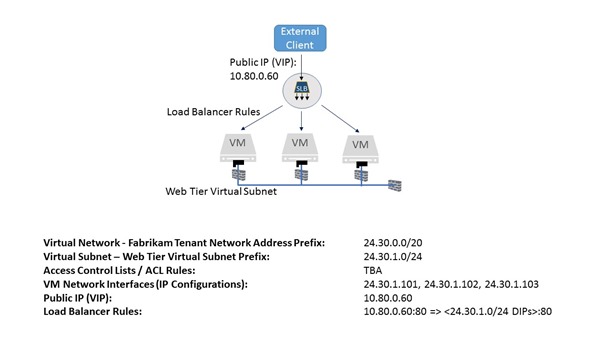
We will be creating the following tenant resources for the front-end web tier of the Passport Expeditor as shown in Figure 1 below.
 Figure 1: Passport Expeditor front end web tier tenant resources
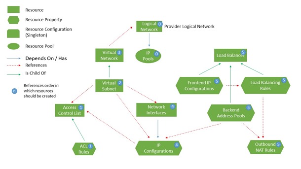
While the network controller can be configured manually to service the application, using automation tools is one of the important facets of cloud-style operations: avoid manual task execution. As with configuring the network fabric resources in the provider context we’ll use the PowerShell scripts on the Microsoft SDN GitHub repository to do the work for us in the tenant context – in this article it’s the SDNExpressTenant.ps1 script TechNet that covers all the details of the automation tools. The resource model for the tenant resources is described in Figure 2. This diagram is a useful reference for when you’re developing automation tools for your environment because it conveys the dependencies.
 Figure 2: Tenant resource hierarchy for the northbound network controller API
The SDNExpressTenant.ps1 script will create these resources with the properties specified below, and we’ll walk through each item in detail:
The front-end web tier contains components closest to the end users and is therefore in the highest risk area. We will use ACLs to manage access to the tier and assign rules to the virtual subnet resource. We only want external users to be able to access the IIS web tier through TCP port 80, and the middle and back-end tiers must be inaccessible from the external network.
Based on the front-end web tier having a virtual subnet IP prefix of 24.30.1.0/24, we will create the following access control list entries.
| Source IP | Destination IP | Protocol | Source Port | Destination Port | Direction | Action | Priority |
| * | 24.30.1.0/24 | TCP | * | 80 | Inbound | Allow | 100 |
| 24.30.1.0/24 | 24.30.2.0/24 | TCP | * | 4500 | Outbound | Allow | 110 |
| * | * | All | * | * | Inbound | Block | 120 |
| * | * | All | * | * | Outbound | Block | 130 |
Table 1: Web-Tier access control list for Passport Expeditor application
We will also create an ALLOW ALL ACL list for testing purposes to validate connectivity. Once connectivity has been verified these rules should be disabled.
| Source IP | Destination IP | Protocol | Source Port | Destination Port | Direction | Action | Priority |
| * | * | All | * | * | Inbound | Allow | 100 |
| * | * | All | * | * | Outbound | Allow | 101 |
Table 2: Connectivity testing access control list
The following PowerShell commands will create these Access Control Lists based on the virtual subnet IP prefix given above (24.30.1.0/24). Record the PowerShell commands in a file so that you can use it later on in the configuration exercise.
The first step in creating an Access Control List (ACL) is to create an array of ACL rules. Figure 3 contains the PowerShell code for our example. Each rule requires the following parameters to be specified:
| Web Tier ACL RulesPS C:\> @aclRules = @()PS C:\ > $aclRules += New-NCAccessControlListRule –Protocol “TCP” –SourcePortRange “0-65535” –DestinationPortRange “80” –sourceAddressPrefix “*” –destinationAddressPrefix “24.30.1.0/24” –Action “Allow” –ACLType “Inbound” –Logging $true –Priority 100PS C:\ > $aclRules += New-NCAccessControlListRule –Protocol “TCP” –SourcePortRange “0-65535” –DestinationPortRange “4500” –sourceAddressPrefix “24.30.1.0/24” –destinationAddressPrefix “24.30.2.0/24” –Action “Allow” –ACLType “Outbound” –Logging $true –Priority 110
PS C:\ > $aclRules += New-NCAccessControlListRule –Protocol “ALL” –SourcePortRange “0-65535” –DestinationPortRange “0-65535” –sourceAddressPrefix “*” –destinationAddressPrefix “*” –Action “Block” –ACLType “Inbound” –Logging $true –Priority 120 PS C:\ > $aclRules += New-NCAccessControlListRule –Protocol “ALL” –SourcePortRange “0-65535” –DestinationPortRange “0-65535” –sourceAddressPrefix “*” –destinationAddressPrefix “*” –Action “Block” –ACLType “Outbound” –Logging $true –Priority 130 PS C:\ > $webTierAcl = New-NCAccessControlList –resourceId “restrictedWebTierAcl” –AccessControlListRules $aclRules Allow All ACL Rules (for testing) PS C:\> @aclRules = @() PS C:\ > $aclRules += New-NCAccessControlListRule –Protocol “ALL” –SourcePortRange “0-65535” –DestinationPortRange “0-65535” –sourceAddressPrefix “*” –destinationAddressPrefix “*” –Action “Allow” –ACLType “Inbound” –Logging $true –Priority 100 PS C:\ > $aclRules += New-NCAccessControlListRule –Protocol “ALL” –SourcePortRange “0-65535” –DestinationPortRange “0-65535” –sourceAddressPrefix “*” –destinationAddressPrefix “*” –Action “Allow” –ACLType “Outbound” –Logging $true –Priority 101 PS C:\ > $allowAllAcl = New-NCAccessControlList –resourceId “allowAllAcl” –AccessControlListRules $aclRules |
Figure 3: ACL configuration using PowerShell
We will apply these access control lists to the virtual subnet of the web-tier below.
The Fabrikam Expeditor Service uses the 24.30.0.0/20 IP network for its entire range. This virtual network will then be subnetted into three smaller networks: one per tier.
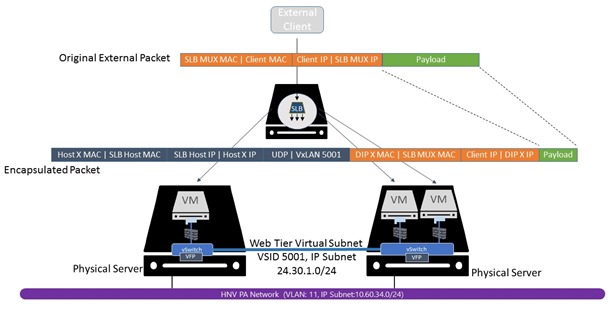
The L2 overlay virtual networks associated with these IP networks will only have network traffic originating from, or destined to VMs attached to the network. Packets on the virtual network will then be encapsulated with a header, dependent upon the network overlay technology chosen: VxLAN (default) or NVGRE, and placed on the wire as shown in Figure 4 below. IP addresses associated with the Provider Address (PA) are on the outside of the encapsulation envelope and IP addresses associated with the Customer Address (CA) are on the inside. If you inspect the network segment using a protocol analyzer, you will see network traffic using the PA ranges on the underlay network.
 Figure 4: Overlay virtual network encapsulation
The PowerShell pseudo code shown below will be used to create the virtual subnets and virtual network. This will be combined with information about the logical network identifiers in Table 1 to yield the complete script.
| Web Tier Virtual Subnet$Provider_LogicalNetwork = get-NCLogicalNetwork -resourceId <PA Logical Network Resource Id>@vSubnets = @()$vSubnets += New-NCVirtualSubnet -ResourceId “WebTierVirtualSubnet” -AddressPrefix “24.30.1.0/24” -AccessControlList $webTierAcl
$vnet = New-NCVirtualNetwork -resourceID “Fabrikam_Vnet1” -addressPrefixes “24.30.0.0/20” -LogicalNetwork $Provider_LogicalNetwork -VirtualSubnets $vSubnets |
Figure 5: PowerShell pseudo code script to configure Web Tier virtual subnet
Each tenant-side virtual network maps to a provider-side logical network. The network controller will create a mapping of CA:PA IP addresses and push this down to the Network Controller Host Agent. The Host Agent will then program this mapping into the Hyper-V Virtual switch’s flow engine. Notice the virtual network’s reference to the logical network we created in Part 1 of this blog post series and the virtual subnet’s reference to the Access Control List created above.
It is important that the Port Profile is created on the physical host after the VM network interface resources have been created on the Network Controller. The port profile ID must match the instance ID of the VM network interface resource. The port profiles are automatically created using the SDNExpressTenant scripts found in the Microsoft/SDN GitHub repository.
A VM Network interface references a port profile ID, and virtual subnet; then are assigned an IP address and a MAC Address. The interface can also optionally reference an Access Control List (ACL) and DNS Server. This level of abstraction from the actual configuration allows ACLs and addresses to follow the VM wherever it is in the tenant infrastructure.
We will use these values for the VM NICs and attaching them to the virtual subnet resource created earlier.
| IP Address | MAC Address | Port Profile ID |
| 24.30.1.101 | 00-15-5D-3A-55-01 | 6daca142-7d94-0000-1111-c38c0141be06 |
| 24.30.1.102 | 00-15-5D-3A-55-02 | e8425781-5f40-0000-1111-88b7bc7620ca |
| 24.30.1.103 | 00-15-5D-3A-55-03 | 334b8585-e6c7-0000-1111-ccb84a842922 |
Table 3: VM network interfaces
We can now combine the PowerShell script structure with the VM NIC details to create the final script that will configure the VMs.
| Web Tier VM NICs$vnet = Get-NCVirtualNetwork –ResourceId “Fabrikam_VNet1”$vsubnet = Get-NCVirtualSubnet –VirtualNetwork $vnet –ResourceId “WebTier_Subnet”$vnics = @()
$vnics += New-NCNetworkInterface –resourceId “6daca142-7d94-0000-1111-c38c0141be06 -Subnet $vsubnet –IPAddress “24.30.1.101” –MACAddress “00155D3A5501” $vnics += New-NCNetworkInterface –resourceId “e8425781-5f40-0000-1111-88b7bc7620ca -Subnet $vsubnet –IPAddress “24.30.1.102” –MACAddress “00155D3A5502” $vnics += New-NCNetworkInterface –resourceId “334b8585-e6c7-0000-1111-ccb84a842922 -Subnet $vsubnet –IPAddress “24.30.1.103” –MACAddress “00155D3A5503” |
At this point the web tier application infrastructure is complete.
The public virtual IP address (VIP) will be used by external clients to access the front-end web tier of the Passport Expeditor Service. This VIP must be within the range of the IP pools (prefix) referenced by the VIP logical subnet created in Part I. The VIP will only be known by the Software Load Balancer Multiplexer (mux). Using internal BGP peering, the SLB mux will advertise the route(s) to the VIP address to a Top-of-Rack (ToR) switch or Routing and Remote Access Services (RRAS) VM. The next-hop for the VIP in the routing table will be the SLB mux. Therefore, as long as packets from external clients destined for the VIP are routed to the ToR switch or RRAS VM (BGP Peer) they will then be forwarded onto the SLB mux. The SLB mux will rely on the L4 load balancing rule resources programmed in the Network Controller to send the packets to the back-end Dynamic IPs (DIP).
In this case, we will create a Public IP (VIP) of 10.80.0.102 from the IP pool (prefix) of the VIP logical subnet using the Front-end IP Configuration resource.
Along with the Public IP address is a set of load balancer rules. These load balancing rules will map a particular IP and port in the VIP to a set of back-end Dynamic IP (DIP) and ports. As previously stated, the VIP comes from a publically routable IP prefix (VIP logical subnet) while the DIPs come from the virtual subnet’s IP configurations assigned to the VM NICs.
We will map the VIP of 10.80.0.102 on TCP port 80 to the back-end IPs of 24.30.1.101, 24.30.1.102, and 24.30.1.103 attached to the front-end web tier’s virtual subnet.
| Load Balancer Configuration$VIP_LogicalNetwork = get-NCLogicalNetwork -resourceId <VIP Logical Network Resource Id>Load Balancer Front-End IP (VIP)$lbfe = @()
$lbfe += New-NCLoadBalancerFrontEndIPConfiguration -PrivateIPAddress “10.80.0. Load Balancer Back-end Address Pool (VM NIC IPs) $ips = @() $vnic = get-NCNetworkInterface -resourceId “4a771202-96e4-4bed-85e6-5ae813b250ca“ $ips += $vnic.properties.ipConfigurations[0] $vnic = get-NCNetworkInterface -resourceId “a7a4470e-7248-471e-a88e-6d95d25a928c” $ips += $vnic.properties.ipConfigurations[0] $vnic = get-NCNetworkInterface -resourceId “dff9075f-eb3e-4cac-b097-cddcdb1a3fd5” $ips += $vnic.properties.ipConfigurations[0] $lbbe = @() $lbbe += New-NCLoadBalancerBackendAddressPool -IPConfigurations $ips Load Balancer Rules $rules = @() $rules += New-NCLoadBalancerLoadBalancingRule -protocol “TCP” -frontendPort 80 -backendport 80 -enableFloatingIP $False -frontEndIPConfigurations $lbfe -backendAddressPool $lbbe $onats = @() $onats += New-NCLoadBalancerOutboundNatRule -frontendipconfigurations $lbfe -backendaddresspool $lbbe $lb = New-NCLoadBalancer -ResourceID “Fabrikam_SLB” -frontendipconfigurations $lbfe -backendaddresspools $lbbe -loadbalancingrules $rules -outboundnatrules $onats |
Figure 6: Load balancer configuration
To validate your configuration, you can invoke one of the Network Controller REST Wrappers: Get-NCLoadBalancer. Ensure that the front-end IP configuration has provisioningState “Succeeded” as shown below.
| PS C:\Deployment\SDNExpress\scripts> . .\NetworkControllerRESTWrappers.ps1PS C:\Deployment\SDNExpress\scripts> $lbconfig = Get-NCLoadBalancerPS C:\Deployment\SDNExpress\scripts> $lbconfig.properties.frontendIPConfigurations |convertto-json -depth 8{
“resourceRef”: “/loadBalancers/Fabrikam_SLB/frontendIPConfigurations/b8886824-aff8-4fa7-b53f-3318d90a8ea6”, “resourceId”: “b8886824-aff8-4fa7-b53f-3318d90a8ea6”, “etag”: “W/\”3d8a916a-aae2-4871-b4f7-f49b76fc73d4\””, “instanceId”: “09feee8a-35a3-4548-a299-4810855d584a”, “properties”: { “provisioningState”: “Succeeded”, “privateIPAddress”: “10.80.0.102”, “privateIPAllocationMethod”: “Static”, “subnet”: { “resourceRef”: “/logicalnetworks/f8f67956-3906-4303-94c5-09cf91e7e311/subnets/ab5add09-9724-4910-9fb3-aa20e4fd0333” }, … } |
You can also check that the load balancing rules are correct.
| PS C:\Deployment\SDNExpress\scripts> $lbconfig = Get-NCLoadBalancerPS C:\Deployment\SDNExpress\scripts>$lbconfig.properties.loadBalancingRules|convertto-json -depth 8{“resourceRef”: “/loadBalancers/Fabrikam_SLB/loadBalancingRules/075a7892-0ba5-44ca-9ff7-b23cdbffc306”,
“resourceId”: “075a7892-0ba5-44ca-9ff7-b23cdbffc306”, “etag”: “W/\”3d8a916a-aae2-4871-b4f7-f49b76fc73d4\””, “instanceId”: “002548af-0eb5-4e74-bdfe-2fdcbc8ab14b”, “properties”: { “provisioningState”: “Succeeded”, “frontendIPConfigurations”: [ { “resourceRef”: “/loadBalancers/Fabrikam_SLB/frontendIPConfigurations/b8886824-aff8-4fa7-b53f-3318d90a8ea6” } ], “protocol”: “Tcp”, “frontendPort”: 80, “backendPort”: 80, “enableFloatingIP”: false, “idleTimeoutInMinutes”: 4, “backendAddressPool”: { “resourceRef”: “/loadBalancers/Fabrikam_SLB/backendAddressPools/2c55c1b2-e371-4a3d-bc74-7f0952b55726” }, “loadDistribution”: “Default” } } |
Now that the network policy for the front-end web tier has been confirmed we can install IIS on the workload VMs (DIPs) to test the policy through the front-end VIP. Let’s send an HTTP GET to the web server to test connectivity. The GET request flows through the load balancer, across the fabric, to the DIP and back to the client (bypassing the SLB Mux for Direct Server Return). This means that the configuration is complete and the web tier is functional. If you refresh the page and/or create new connections, each new connection will be sent to a different back-end DIP VM.
In this post, we quickly deployed a new front-end web tier and created the network policy in a matter of minutes. We also demonstrated some of the security features in the new SDN Stack. In the next blog post, we will show how to create the middle-tier and demonstrate flexibility to scale-up and scale-down resources as required.